ARCHIVE ID
CD-THR-2024-02
CATEGORY
ControlDeck
STATUS
Active
CONDITION
Operational
THRUST
Targeted High-velocity Reactive Unit System Trajectory
Analysis
THRUST Interface Analysis Structure
Advanced overlay visualization revealing thrust vector directions and force magnitude indicators across multi-axis control system. Shows directional force application, delta-v calculations, and thrust vectoring visualization for six-degree-of-freedom manipulation.
THRUST Interface Analysis Energy
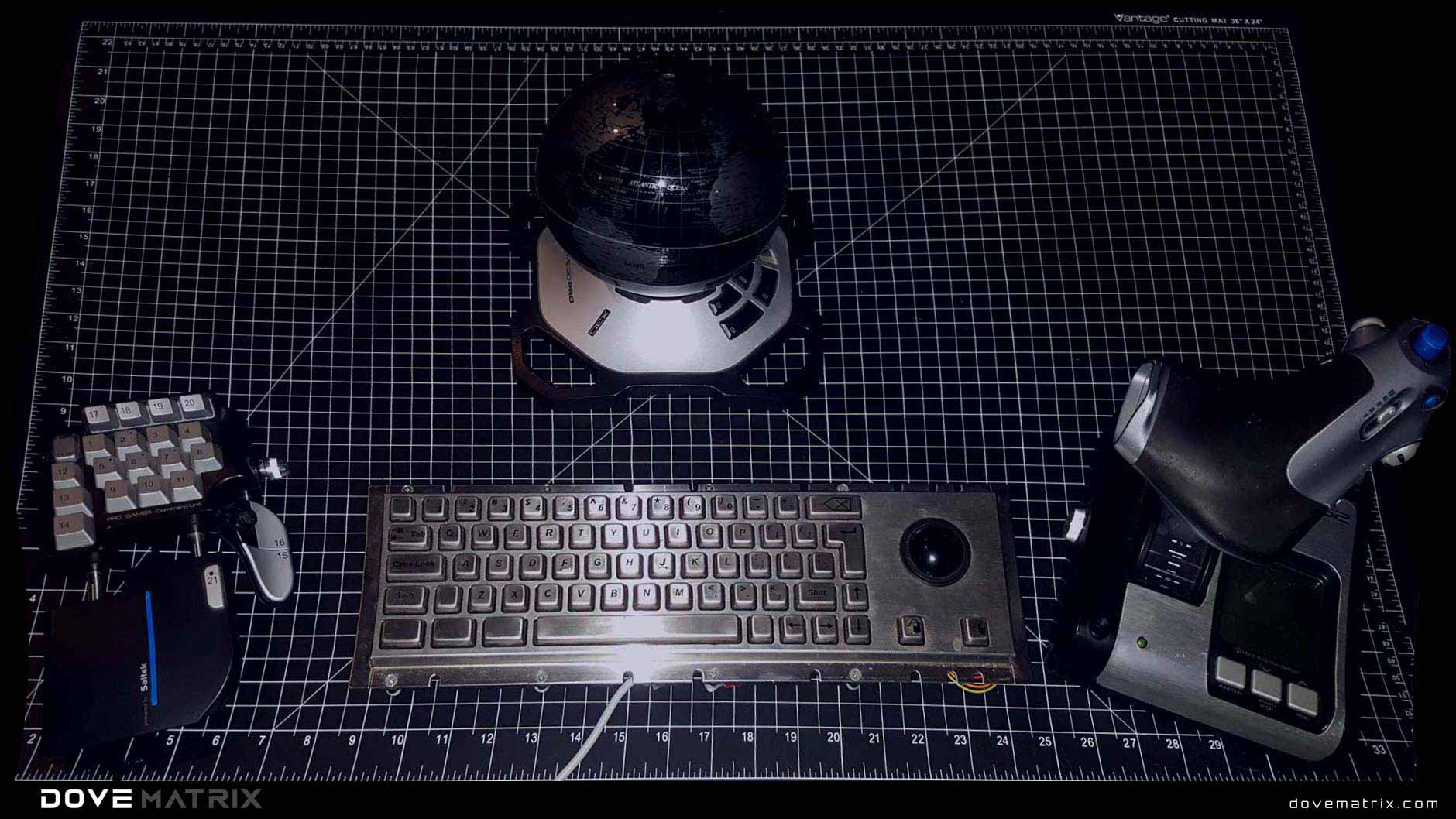
Standard diagnostic mode displaying the THRUST directional force management interface in its primary operational state. Vector control systems and propulsion interfaces visible for baseline force application analysis and momentum transfer capabilities.
THRUST Interface Analysis Signal
Internal circuitry and control pathway analysis exposing force feedback actuators, dual joystick mechanisms, and propulsion calculation processors. Shows six-degree-of-freedom control architecture and vector computation circuits within interface housing.
Profile
Overview
THRUST is a directional force management interface for vector control and propulsion systems enabling precise manipulation of force vectors and momentum transfers. Unlike simple throttle controls, THRUST embodies directional force as primary interface metaphor, treating momentum as controllable resource requiring precision management through multi-axis vector visualization with clear directional indicators.
The device integrates six-degree-of-freedom control system managing translation and rotation simultaneously through dual joystick configuration. Features include force feedback actuators providing physical resistance proportional to commanded thrust magnitude, propulsion calculators integrating velocity, mass, and trajectory data for real-time delta-v computations, precision thrust vectoring across forward, lateral, and vertical thruster banks, and power limit enforcement preventing thrust commands from exceeding safety thresholds or damaging propulsion systems.
Architecture
The THRUST operational architecture employs continuous vector computation where directional force commands are translated into thruster firing sequences. Core functions include joystick position translation to thrust vector coordinates, force magnitude scaling based on control input intensity, delta-v computation integrating current velocity with commanded acceleration, power distribution optimization across available thruster banks, and force feedback generation providing tactile confirmation of thrust application through proportional actuator resistance.
Activation requires thruster system verification and ignition sequence completion before force commands commence. The device maintains continuous monitoring of thrust execution states, calculating real-time velocity changes while enforcing power limit boundaries that prevent excessive thrust commands, ensuring operator inputs remain within safe operational envelopes while maintaining precise six-degree-of-freedom control authority across all translation and rotation axes.
Behavior
Device calibration requires joystick zero-point establishment and force feedback amplitude normalization to maintain thrust control accuracy. Primary calibration involves per-axis neutral position verification, force feedback resistance curve mapping, power limit threshold configuration, and delta-v computation parameter tuning accounting for vehicle mass and thruster performance characteristics specific to current operational configuration.
Regular recalibration is recommended every 80 operational hours or after thruster maintenance to account for propulsion system performance changes. Calibration protocol includes joystick neutral drift measurement, force feedback actuator response testing across full resistance range, power limit verification against thruster specifications, and delta-v computation validation comparing predicted velocity changes with actual telemetry data from test firings.